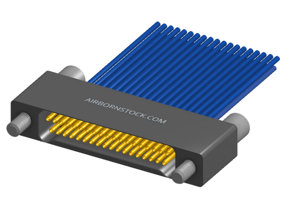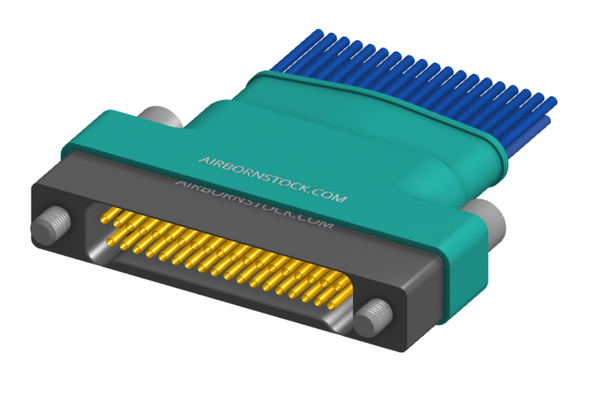


NK-2C5-037-125-0000 - Nano-miniature D-shaped horizontal surface board mount (SMT) connector with mounting holes, 2 rows with 37 contacts, and no hardware. (Plug)
Min. Order Quantity: 7
Lead Time: 6-8 months
| Qty | Price (USD) | Discount | Ext. Price (USD) |
|---|---|---|---|
| 1 | $1,149.99 | - | - |
| 10 | $1,057.99 | -- | |
| 25 | $1,011.99 | -- | |
| 50 | $862.49 | -- | |
| 100 | $770.49 | -- | |
| 250 | $632.49 | -- | |
| 500 | $517.50 | -- | |
| 1,000 | $460.00 | -- |
--
Couldn't load pickup availability
Payment & Security
Payment methods
Your payment information is processed securely. We do not store credit card details nor have access to your credit card information.
Availability
Availability
Our minimum required order quantity is seven (7) pieces.
Average lead time is 6-8 weeks from time of order.
If a portion of your order is already in stock, we will ship that immediately, with the remainder of your order being shipped once back in stock.
Products will ship from JRH Electronics, a Molex (AirBorn) authorized distributor.
Standard, expedited, and express delivery options are available. See shipping rates.
Gender

# Positions
# Rows
Orientation

Termination

RoHS?

Product Description
Nano-D .025" (N Series)
Pitch spacing between contacts on AirBorn's Nano product line is 0.025" (0.64mm).
The AirBorn Nano-Connector Series is a line of high-performance connectors designed for applications where size, weight, and reliability are critical.
Key Features:
- Compact Size: Nano-sized connectors with high-density configurations for space-constrained designs.
- High Reliability: Rugged construction designed to withstand harsh environments, including vibration, extreme temperatures, and shock.
- Lightweight: Engineered with lightweight materials, making them ideal for applications where weight savings are crucial.
Applications:
- Aerospace: Avionics systems, UAVs, and space exploration equipment.
- Defense: Mission-critical communication systems and portable electronics.
- Medical: Miniaturized diagnostic and therapeutic devices.
- Industrial: Robotics, sensors, and control systems in tight spaces.
The AirBorn Nano-Connector Series is valued for its exceptional balance of miniaturization and performance, meeting the stringent requirements of high-reliability sectors.
| Plug (Male) | |
|---|---|
|
Series Designator |
|
|
RM |
.075" Screw Machine Connectors |
|
Body |
|
|
Rows |
|
|
2 |
2 Rows |
|
Body Style |
|
|
5 |
Plug, Right Angle, with Mounting Ears |
|
7 |
Plug, Right Angle, without Mounting Ears |
|
Body Material |
|
|
2 |
Polyphenylene sulfide (PPS) |
|
Size |
|
|
010 |
10 Contacts |
|
020 |
20 Contacts |
|
030 |
30 Contacts |
|
040 |
40 Contact |
|
050 |
50 Contacts |
|
060 |
60 Contacts |
|
070 |
70 Contacts |
|
080 |
80 Contacts |
|
090 |
90 Contacts |
|
100 |
100 Contacts |
|
Contacts |
|
|
Contact Type |
|
|
31 |
Pin, Right Angle Dip Solder, .109" x .020" dia |
|
32 |
Pin, Right Angle Dip Solder, .140" x .020" dia |
|
33 |
Pin, Right Angle Dip Solder, .172" x .020" dia |
|
34 |
Pin, Right Angle Dip Solder, .109" x .016" dia |
|
35 |
Pin, Right Angle Dip Solder, .140" x .016" dia |
|
36 |
Pin, Right Angle Dip Solder, .172" x .016" dia |
|
37 |
Pin, Right Angle Dip Solder, .250" x .016" dia |
|
Plating Options |
|
|
1 |
Gold Plated Termination |
|
2 |
Pre-Tinned Termination, SnPb alloy |
|
3 |
Pre-Tinned Termination, SAC305 alloy |
|
Hardware |
|
|
Hardware Style |
|
|
0256 |
None |
|
55 |
Guide Set |
|
57 |
Two Guide Pins |
|
58 |
Two Guide Sockets |
|
29 |
Fixed Jackset |
|
30 |
Fixed Jackset, Reversed |
|
19 |
Two Fixed Jackscrews |
|
20 |
Two Fixed Jacksockets |
|
59 |
Hex Turning Jackset, .200" |
|
60 |
Hex Turning Jackset, Reversed .200" |
|
61 |
Two Hex Turning Jackscrews, .200" |
|
62 |
Two Hex Turning Jacksockets, .200" |
|
64 |
Turning Jackset, .490" |
|
65 |
Turning Jackset, Reversed, .490" |
|
66 |
Two Turning Jackscrews, .490" |
|
67 |
Two Turning Jackscockets, .490" |
|
Polarization |
|
|
00 |
None |
|
01 |
Keying Position - 01 |
|
02 |
Keying Position - 02 |
|
03 |
Keying Position - 03 |
|
04 |
Keying Position - 04 |
|
05 |
Keying Position - 05 |
|
06 |
Keying Position - 06 |
|
07 |
Keying Position - 07 |
|
08 |
Keying Position - 08 |
|
09 |
Keying Position - 09 |
|
11 |
Keying Position - 11 |
|
12 |
Keying Position - 12 |
|
13 |
Keying Position - 13 |
|
14 |
Keying Position - 14 |
|
15 |
Keying Position - 15 |
|
16 |
Keying Position - 16 |
|
17 |
Keying Position - 17 |
|
18 |
Keying Position - 18 |
|
19 |
Keying Position - 19 |
|
20 |
Keying Position - 20 |
|
21 |
Keying Position - 21 |
|
22 |
Keying Position - 22 |
|
23 |
Keying Position - 23 |
|
24 |
Keying Position - 24 |
|
25 |
Keying Position - 25 |
|
26 |
Keying Position - 26 |
|
27 |
Keying Position - 27 |
|
28 |
Keying Position - 28 |
|
29 |
Keying Position - 29 |
|
30 |
Keying Position - 30 |
|
31 |
Keying Position - 31 |
|
32 |
Keying Position - 32 |
|
33 |
Keying Position - 33 |
|
34 |
Keying Position - 34 |
|
35 |
Keying Position - 35 |
|
36 |
Keying Position - 36 |
|
37 |
Keying Position - 37 |
|
38 |
Keying Position - 38 |
|
39 |
Keying Position - 39 |
|
40 |
Keying Position - 40 |
|
41 |
Keying Position - 41 |
|
42 |
Keying Position - 42 |
|
43 |
Keying Position - 43 |
|
44 |
Keying Position - 44 |
|
45 |
Keying Position - 45 |
|
46 |
Keying Position - 46 |
|
47 |
Keying Position - 47 |
|
48 |
Keying Position - 48 |
|
49 |
Keying Position - 49 |
|
50 |
Keying Position - 50 |
|
51 |
Keying Position - 51 |
|
52 |
Keying Position - 52 |
|
53 |
Keying Position - 53 |
|
54 |
Keying Position - 54 |
|
55 |
Keying Position - 55 |
|
56 |
Keying Position - 56 |
|
57 |
Keying Position - 57 |
|
58 |
Keying Position - 58 |
|
59 |
Keying Position - 59 |
|
60 |
Keying Position - 60 |
|
61 |
Keying Position - 61 |
|
62 |
Keying Position - 62 |
|
63 |
Keying Position - 63 |
|
64 |
Keying Position - 64 |
|
65 |
Keying Position - 65 |
|
66 |
Keying Position - 66 |
|
67 |
Keying Position - 67 |
|
68 |
Keying Position - 68 |
|
70 |
Keying Position - 70 |
Catalog Page: ctr010-M (Rev:F)
| PERFORMANCE REFERENCE MIL-DTL-55302 | |
|---|---|
|
CONTACT RATING |
3-amperes (2 amperes for 0.016" diameter) |
|
SOLDERABILITY |
Terminals (except wire wrap, crimp, and stackables) tested in accordance with MIL-STD-202, method 208 |
|
WIRE SIZE |
Stranded #26 AWG |
|
OPERATING TEMPERATURE |
-65°C to +125°C or -85°F to +257°F |
|
TEST VOLTAGE |
750V (RMS) 60 Hz at sea level. 250V (RMS) 60 Hz at 70,000 feet. Tested in accordance with SAE AS 13441, method #3001 |
|
INSULATION RESISTANCE |
5,000 megohms minimum at 500 VDC. Tested in accordance with SAE AS 13441, method #3003 |
|
DURABILITY |
500 connector mating cycles |
|
VIBRATION |
Mated connectors, test condition III. Tested in accordance with SAE AS 13441, method #2005 |
|
SHOCK |
Mated connectors, test condition G. Tested in accordance with SAE AS 13441, method #2004 |
|
SALT SPRAY |
Mated connectors, test condition B. Tested in accordance with SAE AS 13441, method #1001 |
|
HUMIDITY |
Test type II, (except steps 7a and 7b not required). Tested in accordance with SAE AS 13441, method #1002 |
|
TEMPERATURE CYCLING |
Mated connectors, test condition A. Tested in accordance with SAE AS 13441, method #1003 |
|
CONTACT RESISTANCE |
0.015 ohms maximum (interface measurement) at 3 amperes. Tested in accordance with SAE AS 13441, method #3004 |
|
CONTACT MATING FORCE |
2.5 oz. x number of contacts average |
|
OUTGASSING |
The entire connector assembly shall have maximum total mass loss (TML) of 1.0 percent of the original specimen mass and shall have a maximum volatile condensable material (VCM) content of 0.1 percent of the original specimen mass. |
|
SIZES 50 AND LARGER |
Upon engagement, center area of mating faces may remain open 0.010" to 0.025" due to slight flexing of molding. Vibration or shock should provide complete closure. |
|
GUIDES AND JACKS |
If location of pin or socket contacts is reversed, location of male and female guides or jacks is also reversed; except when using D shaped polarized guides. When polarized positions are changed, apply Loctite® 242-12 or equivalent to threads. |
| MATERIALS & FINISHES | |
|---|---|
|
PIN CONTACTS |
BeCu, per ASTM-B196, ASTM B 197/B 197M-, or brass alloy per ASTM B 16/B 16M or ASTM-B134 |
|
SOCKET CONTACTS |
BeCu per ASTM-B194 and/or ASTM-B 196, ASTM B 197/B 197M-, or brass per ASTM B 16/B 16M or ASTM-B134 |
|
CONTACT FINISHES |
Gold plate per ASTM B 488-, SAE AMS 2422, or localized finish per MIL-DTL-55302 and associated slash sheet |
|
SOLDER |
Sn/Pb alloy - 63% tin, 37% lead composition [x]. SAC305 - 96.5% tin, 3% silver, 0.5% copper composition |
|
MOLDED INSULATORS |
Glass filled polyphenylene sulfide per MIL-M-24519, type GST-40F |
|
JACKSCREWS |
Stainless steel per ASTM A 582/A582M-Passivated per ASTM-A967, SAE AMS-QQ-P-35 |
|
JACKSOCKETS |
Stainless steel per ASTM A 582/A582M-Passivated per ASTM-A967, SAE AMS-QQ-P-35 |
|
JACKSCREW KNOBS |
Stainless steel per ASTM A 582/A582M-Passivated per ASTM-A967, SAE AMS-QQ-P-35 |
|
GUIDE PINS, GUIDE SOCKETS |
Stainless steel per ASTM A 582/A582M-Passivated per ASTM-A967, SAE AMS-QQ-P-35 |
|
GUIDE SOCKETS, POLARIZED "D" TYPE |
BeCu per ASTM-B196, ASTM B 197/B 197M-, nickel plated per SAE AMS-QQ-N-290 |
|
CONNECTOR MARKINGS |
Contact numbers are stamped on the side of the connector. Numbers are stamped on the low-numbered side only on 2-row and 3-row right-angle connectors. |
|
TOLERANCES |
Angles: ±5°, |
Product Datasheets
#REF!
Mating Connectors
The following is a list of connectors, organized by termination type, that mate with this connector.
I/O Connectors
Crimp Termination